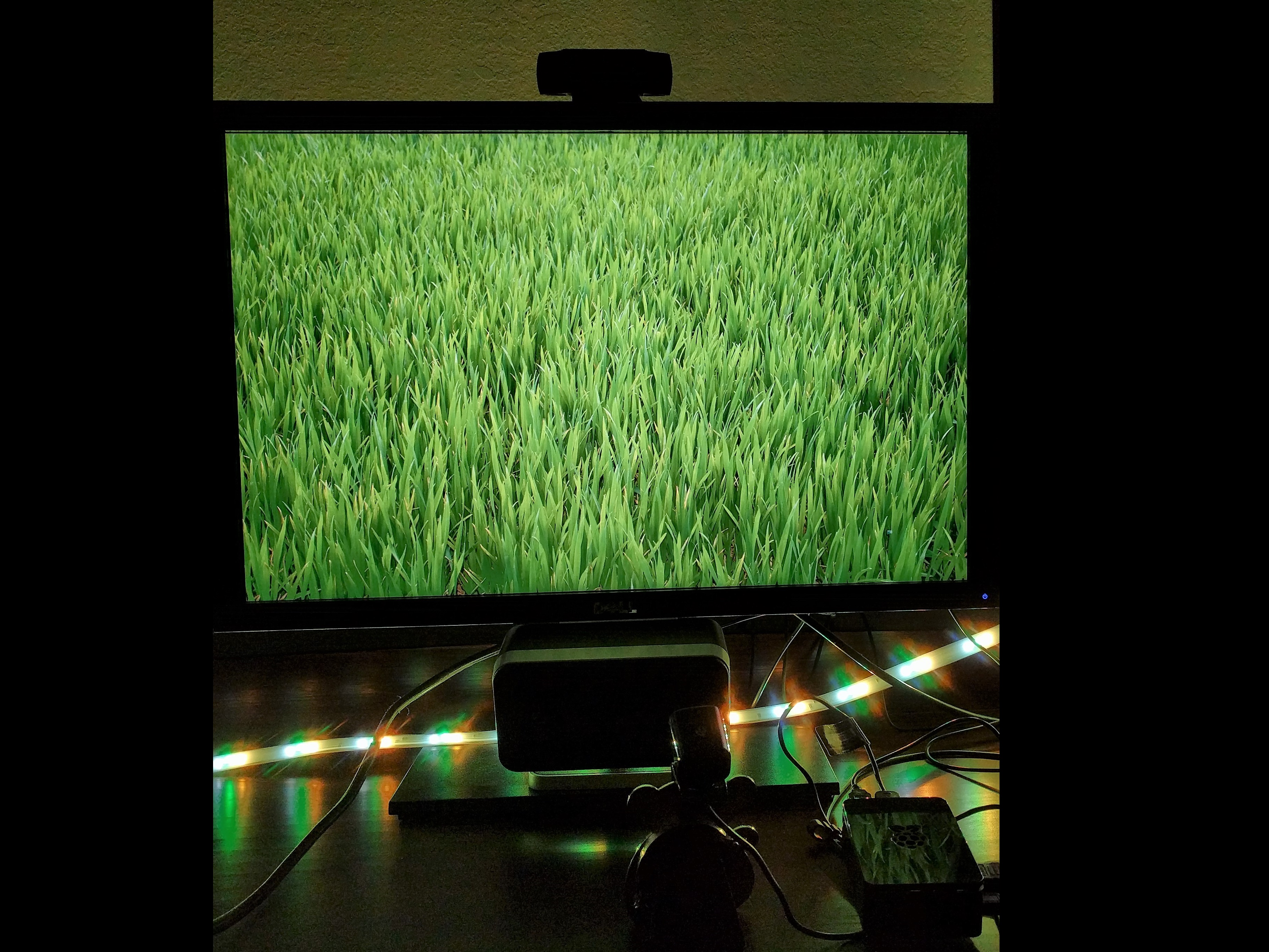
- #Raspberry pi ambient light install
- #Raspberry pi ambient light serial
- #Raspberry pi ambient light driver
- #Raspberry pi ambient light upgrade
- #Raspberry pi ambient light code
The Arduino projects are located at the path ~/Arduino/…Ĭopy the folder in the Arduino directory to the library in the Arduino installation directory.
#Raspberry pi ambient light serial
Open the serial port assistant software on the computer and select the corresponding port to check the output data:ĭownload the example from Waveshare Wiki and unzip it. The connection is shown in the following table:

The example uses UART3 (PA3, PA3) to output debug information. You can also use STM32CubeMX to port example. h files to implement the functions and acro definitions. If you want to port the examples for other STM32 chip, or change to standard libraries, you can only modify the DEV_Config.c and. The development board used for the test is XNUCLEO-F103RB of Waveshare, wich chip is STM32F103RBT6. Open \XNUCLEO-F103RB\MDK-ARM\demo.uvprojx project with Keil uVision5. The STM32 projects are located at the path ~/STM32/… Sudo chmod 777 -R TSL2591X_Light_Sensor_codeĭownload the example from Waveshare Wiki and unzip it.
#Raspberry pi ambient light install
Hardware connection TCS34725 Color Sensorĭownload and run the test examples sudo apt-get install p7zip-fullħz x TSL2591X_Light_Sensor_code.7z -r -o./TSL2591X_Light_Sensor_code #Running gpio -v will appear version 2.52.
#Raspberry pi ambient light upgrade
#For Raspberry Pi 4B, an upgrade may be required: # For more code, please refer to our official website
#Raspberry pi ambient light driver
Select Interfacing Options -> i2c-> yes to start the I2C driver
#Raspberry pi ambient light code

By following, the Host sends the data to the Slave. Stop signal: When SCL is HIGH and SDA jumps from LOW to HIGH, the data transmission stops.Īck signal: When the receiver IC have received 8 bit of data, it will send out a special LOW level pulse to the transmitter IC to indicate that the data have been received.Īt the beginning, the Host (here is STM32, and we will call it the Host hereafter) sends out a start signal, and combines the 7 bit of I2C slave address with the Write bit, then, sends this 8 bit of data to the Slave (here is TSL2581 sensor, and we will refer it to the Slave hereafter). Start signal: When SCL is HIGH and SDA jumps from HIGH to LOW, the data transmission starts. They are Start signal, Stop signal, and Ack signal. There are three types of signals will be used during the I2C bus data transmissing. TSL2591 use I2C interface, has a data line and a clock signal line. The digital output can be inputted to a microprocessor where an empirical formula is used to derive illuminance in lux (ambient light level) to approximate the human eye response. Two integral ADCs convert the photodiode current into a digital output representing the irradiance measured on each channel. The sensor combines a wideband photodiode (visible and infrared) and an infrared response photodiode on a single CMOS integrated circuit that provides near-light adaptive response over an effective 16-bit dynamic range (16-bit resolution). This product uses TSL25911FN, which is a light intensity digitizer based on IIC bus communication.

It can sense the ambient light intensity around and output it through the I2C interface. This module is an ambient light sensor with TSL25911 as its core.


 0 kommentar(er)
